Page 1 of 2
Maintain volume joint proposal
Posted: Tue Jan 20, 2009 3:24 pm
by heyvern
This is a rough concept for an addition to bones to control joint volume on limbs:
1. Select a bone that is part of a joint for a limb.
2. Open the Constraints dialog box
3. In the bone angle boxes set the min (start) and max (end) angles to control scaling of the selected points
4. set the offset (x,y) for the center of the joint envelope
5. set the radius of the joint control envelope
6. set the amount of scaling to be applied by the joint control


-vern
Posted: Tue Jan 20, 2009 4:20 pm
by mkelley
Okay, if this is how you see it implemented I don't care as long as it works (because it's imaginary we can all pretend it works just fine).
However -- I would add this one simple request to all this: a checkbox (somewhere?) that, if checked (the default) will not allow an object's outside border lines to cross themselves.
Because that's really the whole bottom line with any of these joints -- creasing the joint too much and the lines intersect. And I have no idea of the math involved or what programming needs to be done, only that it fits in your idea of "an example" of how things should work.
Once again -- if the box is checked the object's lines never cross. Never -- verts just slide down to avoid this crossing. I don't particularly care how it's accomplished, because that will do all I need it to do.
Posted: Tue Jan 20, 2009 6:05 pm
by DK
Mkelley wrote:
However -- I would add this one simple request to all this: a checkbox (somewhere?) that, if checked (the default) will not allow an object's outside border lines to cross themselves.
That would be brilliant....especially for collapsing objects onto ground planes. A footbone for example. You could set it so that when the foot impacted a outline it would flatten out.....I can think of quite a few areas this would be usefull in animation.
Vern....that graphic sim is so good i want it there now!!!!
Cheers
D.K
Posted: Tue Jan 20, 2009 6:31 pm
by Víctor Paredes
It looks great, I'm glad that the discussion start to generate good ideas.
Just one little addition, I think, maybe it should be more graphic, I mean, you could scale and move the circle dragging the mouse too, It would make it easier for people less... numeric.
Posted: Wed Jan 21, 2009 8:25 am
by Genete
OK, this will be difficult to explain without graphic aids, but I think it is worth to try.
What Vern's is proposing is to give a relative linear translation and radial scale to the points that the user want to belong to the joint.
So the point motion is give by the bone motion plus a translate-scale additional movement from the joint center.
My proposal is similar but I'll give it a plus. I propose that the additional movement of the point given by the joint angle were not linear but given by a custom defined curve.
How? so simple.
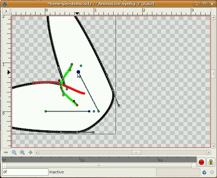
Look to first image from Vern.
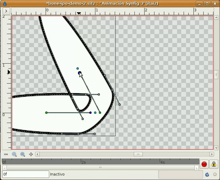
Those three selected (red) points have a particular position when the joint is extended. They have a different position in the second image when the joint is flexed.
When Vern created both images he added some point motion to the three points to place them in the desired position. Let's say he just have moved the points (point motion) when the joint was at its maximum angle. So he has added a single keyframe at the frame where the joint was flexed. Let's assume that it was done at frame 12.
If he drags out the arm layer form the bone layer he could see the effective translation he produced to those points to achieve that adjustment to fit the correct joint shape. Even he can see that the translation from the original position to the final position is linear. From frame 0 to frame 12. Imagine that for some reason at frame 6 the points doesn't look fine. The usual way to solve that is go to frame 6 and tweak the points again. If the travel is larger the amount of tweaks can be increased. What I propose is that those tweaks (usually non linear movements) were governed by the joint angle and repeted in any other place in the timeline and in any intermediate position of the joint angle.
How? similar to the follow path to the layer translation.
If a layer origin can follow a path why not a point can follow a path too? Imagine that everytime you tweak a point you're tweaking its path instead. And when the user manipulates the bone in the frame 0 the point with paths assciated follow the bone motion plus the path motion.
Does it make sense?
It is very similar to what is called IPO-drivers in Blender.
http://www.blender.org/development/rele ... o-drivers/
-G
Posted: Wed Jan 21, 2009 9:32 am
by mkelley
Oooo, if I follow you this is *exactly* what I proposed in the first place.
Let me see if I can make my own translation (not that you need any, but just to see if I'm right). What we do is define the position of the points at the extreme positions, and the program interpolates between those positions. Which is what I said (in my own way) when I said I wanted to define the cross sections of the limb as it deforms.
IOW, in a 3D program we say that when a joint reaches a certain position (in this case 90 degrees) the cross section looks like this, and then the program itself determines the interpolation between that cross section and the "normal" or at rest position. That's all I ever wanted and I think that's what you're proposing -- allowing us to define where the verts should end up when the joint is deformed.
I don't know how to show this, but I do think you've said it better than I did. Perhaps Vern will understand as well and be able to show it graphically, because I think this is all we ever need (which is to say just the ability to control where the verts end up at whatever angle of deformation we want and let the program interpolate the rest).
Posted: Wed Jan 21, 2009 11:46 am
by heyvern
First off I left a TON of questions about this unanswered. I realize that the scaling of the joint "circle" would spread those points OUT instead of in. We need some kind of "contraction and expansion. Like as if the out edges of the circle contracted inwards on the radius of the circle as it is pushed out and up? It's very complicated to think about.
My personal opinion is that a single dedicated feature like this is way more complicated than anyone thinks. It involves bunches of things happening together to give a single very specific result. None of those smaller things can be used alone. You end up with just this one joint expansion feature.
If all the "features" needed to make this work were available by themselves as smaller features that would be better than a one trick pony... in my humble opinion.
3D polygon models with joints is totally different and doesn't really apply. Those models are made up of a very dense mesh of triangles. The whole model is controlled by bones. There is no "point" motion. A lot of the 3D solutions involve "morph" targets. Maybe that would be a solution here? Use a "pose" controlled by the rotation of a bone to "morph" to a different joint shape? As the bone rotates you just interpolate to a different set of point positions.
I looked on Google for any reference to that Lightwave "joint" expansion feature and couldn't find it. If someone has a link to a tutorial it might give me some more ideas.
Mike, you mentioned a checkbox to fix the splines at the joint "crossing over" themselves. This is another situation that doesn't have a simple solution. The reason the inside of the joints "bulge" and cross over is due to how the curves behave in AS. The way to solve that problem is through offsetting the position of the points relative to the pivot and each other on opposite sides or having extra points closer to the pivot. Another fix is to reduce the curve setting of the inside point. Controlling the curve of the inside point would be the EASIEST fix.
To fix that problem other than using point curves, would require another feature request involving changes to the curves and bias control on opposite sides of a point. That is moving into "bezier" curve territory or the "Make Dragon" button

. If Mike Clifton is planning to add some new type of curve definition like independent bias control then that inside joint bulge issue can be dealt with later. I don't think at this point bezier curves is on the menu. It would be a nightmare and involve backward compatibility issues and possibly a new type of vector layer. AS would become Flash... ick.
---------
I guess my whole point about this is... I have a joint rig that works really well and maintains volume. But it does require a few bones and is a bit tricky to set up. That is the main complaint from others about using it as a solution. It works for me so I have a solution for this. It's not a perfect solution but it works NOW using multiple smaller features in the program.
My "feature" request wouldn't involve the joint problem specifically but the improving or adding to EXISTING bone constraints/features to reduce the number of bones and constraints needed to create that joint.
Here's what I need to make this easier to do:
- 1. translation limits on bones
2. Child translations constraints that INCLUDE parent rotation offsets
3. Rotation/translation type conversion constraints
4. multiple bone constraint targets
5. Linking bone rotation to point PROPERTIES like curve settings
(a bones rotation controls curve peaking and smoothing)
These are smaller features that are built on top of existing features.
With those features I could come up with an easier fix for the joint problem using just a few bones AND we can use the features individually in other situations (like 2.5d face rigs that don't use 200 bones.
)
Those features will be my next use case but it requires more work. I need to define all those features.
-vern
Posted: Wed Jan 21, 2009 3:50 pm
by Genete
What I'm going to show here is a non complete feature of synfig. It is currently under development: a bone system.
The following videos illustrate how it is possible to define a joint that follows a defined path. The red and green lines are the path that the two target vertices of the joint are linked to. The movement of the vertices along those red and green lines are governed by the bone rotation but can be governed by any other parameter from bones or any other object (synfig allows that).
video demo (2.39 MB):
http://www.mediafire.com/?ntevtnxbp9d
Notice how modifying the path it also modifies the position of the point.
Compare the same structure without the paths. The region crosses itself like usual for this kind of rig.
video demo (1.13 MB):
http://www.mediafire.com/?uwddwglfhym
That's what I was referring to.
-G
Posted: Wed Jan 21, 2009 3:58 pm
by synthsin75
Vern, I want to add one of your older requests to that list. Constrained bones that can be manually manipulated.
Here's an idea (very rough). What if you could define an action from one extreme to the other that could be assigned to run as the bone rotates?
This would be something like Genete's pose array. But it could be similar to mini-timelines.
Posted: Wed Jan 21, 2009 9:23 pm
by heyvern
Synthsin, that's a cool idea, using poses for bone rotation. I love that idea. It is almost identical to "Smart Skin" in Animation Master.
Genete,
That feature for "bones" in Synfig is also cool as heck! I love that idea. I wonder how hard that might be to script in AS??? This could be doable. A non rendering layer over the "limb" layer. Somehow (that's the hard part
) "bind" points from the limb layer to the "guide" layer...
HOLD ON... stop the presses. It wouldn't be another layer just another shape on the same layer...
This is COOL because it is VERY flexible. You can tweak it perfectly very easily for any joint shape or configuration. I don't have a ton of experience scripting vectors but it would be worth it to look into this idea.
p.s. The Synfig creators can't sue me if I "borrow" this idea right?
-vern
Posted: Wed Jan 21, 2009 10:09 pm
by Genete
Vern,
in fact this feature (the "link to bline" one) is not part of the bones feature under development. It exists since the last release. What's new is the application concept of the feature to a point that is influenced by the bone. I just did it yesterday to show the concept of the requested feature.
You or Mike (I should say) are not forbidden to look into the synfig features or its code but (I think) you're obligated to. This bone feature includes some of the dreams of the AS enthusiasts: animated bone re-parenting, animated bone setup, bone width scale, recursive bone length/width scale, support for tangents of bline points, bones visibility when vector layer is selected, bone influence over vector layer at any vector layer position in hierarchy, ... and other goodies not implemented yet

So interesting times are coming!
-G
Posted: Thu Jan 22, 2009 12:57 am
by heyvern
I just did some simple tests with a layer script and that bone feature should work. I am able to find any point ALONG the curve of a line in a vector layer. The location of this "point" is based on a percentage along the curve. So, you pick a spot on the curve based on the rotation of the bone and move a point or points from the joint to that location. Or you could move a bone.
Named groups will work here. According to the script reference you can select point groups by name. Select the group then the curve, then find a point on the curve. As the bone rotates the position of a point based on percentage of rotation is located on the curve.
Hmm... maybe Mike Clifton can use this info in designing the new feature? The functionality exists in the current application. My problem is everything requires a "layer script". How much can you jam into one dang layer script?
Another feature request: Multiple Layer Scripts! or layer scripts that can be stored in the utilities script and referenced in AS without the need for a separate file. A text entry in AS that "calls" a script located in the AS script directory.
-vern
Posted: Thu Jan 22, 2009 1:40 am
by chucky
Multiple Layer Scripts!
Oh I can't believe that wasn't on any of our recent lists.
What were we thinking?
This joint maintenance topic has brought about some great discussion.
Glad to see Genete's time on Synfig has been beneficial on this side of town too.

Posted: Thu Jan 22, 2009 2:08 am
by Genete
chucky wrote:This joint maintenance topic has brought about some great discussion.
Thanks to mkelley's insistence and first Vern's proposal for joints I figured out a good usage of the current features of synfig and its possible application to AS.
chucky wrote:Glad to see Genete's time on Synfig has been beneficial on this side of town too.
I've been always here! I'm sure that my AS and Synfig knowledge will benefit both programs. IMHO competition is always good for everyone. And having a better Synfig on the street would benefit AS development too.
What I only miss from AS is a little more of support form the vendor (not form Mike that I know he is conscient of that) to the linux community.
-G
Posted: Thu Jan 22, 2009 2:16 am
by heyvern
If I were younger or didn't have so much personal investment in AS I might be tempted to give Synfig a try... but... it makes me sleepy thinking about trying something new at this point.
I already have my time split between Animation Master and Anime Studio. I just can't squeeze another program into my schedule.
p.s. Frantically finishing a short animation in Animation Master for the upcoming NYCC. I was surprised to see that Smith Micro was not on the exhibitor's list for that show. It would seem to be the kind of thing they would go to.
The last NYCC I went to I was bouncing back and forth between the Hash booth and the efrontier booth.
-vern